You are here: Building the Model: General Elements > Path Networks > Mapping Edit Table
If there are multiple paths emanating from one node to another node, the default path selection will be based on the shortest distance for speed & distance networks, and the least number of nodes for time based networks. These defaults can be overridden by explicitly mapping some destination nodes to specific branches that entities and resources will take when traveling out of a "from" node.
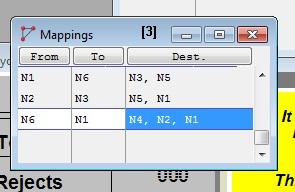
The fields of the Mapping edit table are described as follows.
From Entities and resources traveling out of this node will use this mapping record to decide which of the alternate branches will be taken next.
To The "from" node and the "to" node together define the branch to be taken next. This might also be interpreted as the node which entities and resources will go through, to reach one of the destination nodes.
Dest. Entities and resources whose ultimate destination is one of these nodes will be forced to take the branch that directly connects the "from" node to the "to" node.
Please note
When your simulation is compiled and run, ProModel will automatically define destinations for your network mapping, if you have not defined them yourself. These computer-generated mappings will not appear in the Dest. column of the Mappings table, but the From and To columns will contain information on these mappings. Do not delete the information in these columns.
How to create mappings using the mapping edit table:
1. Click on the Mapping... heading button in the Path Network edit table. This will open the Mapping edit table.
2. Click on the From heading button and select the node to be mapped.
3. Click on the To heading button and select the terminating node for the branch to be mapped.
4. Click on the Destination heading button and select the desired node(s).
How to create mappings graphically:
1. Click on the Mapping... heading button in the Path Network edit table. This will open the Mapping edit table.
2. Click on the from node in the Layout Window. This places the selected node in the From field.
3. Click on the to node in the Layout Window. Note that the to node must be directly connected to the from node with a single branch.
4. Click on the destination node(s) in the Layout Window. This places the selected node(s) in the Destination field.
Please note
ProModel automatically calculates and uses the shortest paths based on time or distance on unmapped portions of networks. If an Expression Array is used to specify the times for a time-based network and the time unit is included as part of the expression in the array, the time unit will not be used when determining the shortest path. In order to have the time unit affect the shortest path calculation it must be explicitly entered in the Time field (e.g. Arr1[1,2] min).
An example of mapping two branches of a network is given on the following pages.